
WARNING: If you attempt any of these upgrades and or modifications to your K40 Laser cutter you will be handling 120V mains power and very high voltages from the main power supply. This can be very dangerous, even lethal. I am in no way responsible for any damage or harm you may cause, whether it be to yourself, others, or your belongings through replicating anything shown here. You the reader agree that by following this build-log and replicating anything you hold yourself and yourself only for any damages or harm caused.
I recently purchased a cheap (<$400) K40 Laser Cutter/Engraver from ebay. This is an okay machine that needs some work to get running well. It does work right out of the box, but you are forced to use CorelDraw for creating the laser-cutting files and for controlling the K40 – and it is not exactly intuitive. If you are here to gather information for upgrading your K40 laser cutter, I suggest that you also join the Google+ group here for a community of people with K40 lasers that are very knowledgeable about the K40 and typical upgrades for it.

I knew going into the purchase that there were upgrades that I wanted to make:
- Switch the motherboard with a Smoothieboard so that I can use LaserWeb for controlling the K40
- Add laser-site assist (cross-hairs to see where the laser is pointed on the bed)
- Change the watercooling to a closed-loop internal system without the need for a large external reservoir
- Add active chilling to the watercooling circuit.
- Add air assist to the laser nozzle for blowing out any flames when cutting wood and for blowing material away to keep the lens clean
- Add internal LED lighting to the cutting area
- Replace exhaust fan with more powerful 12VDC blower
- Add a temperature sensor to the watercooling reservoir to monitor the temperature of the CO2 tube
- Add a mechanical switch to the cover for safety so that the laser cannot be on if the cover is open
- Add drag chain for air assist tubing and laser-site assist wires
- Add an adjustable z-axis table.
Bill of Materials (BOM)
Current BOM for all of the upgrades shown.
Wiring
k40_wiring_diagram_smoothieboard_and_acr
The first thing I noticed when I started looking at the wiring inside the electronics panel was that the ground stud on the inside rear panel of the case was surrounded by paint, so the terminal coming from the AC inlet was not really grounded to the chassis. After removing all of the electronics from inside the panel I took a dremel to the area around the ground pin and removed the paint so the ring terminal made good contact with the chassis.
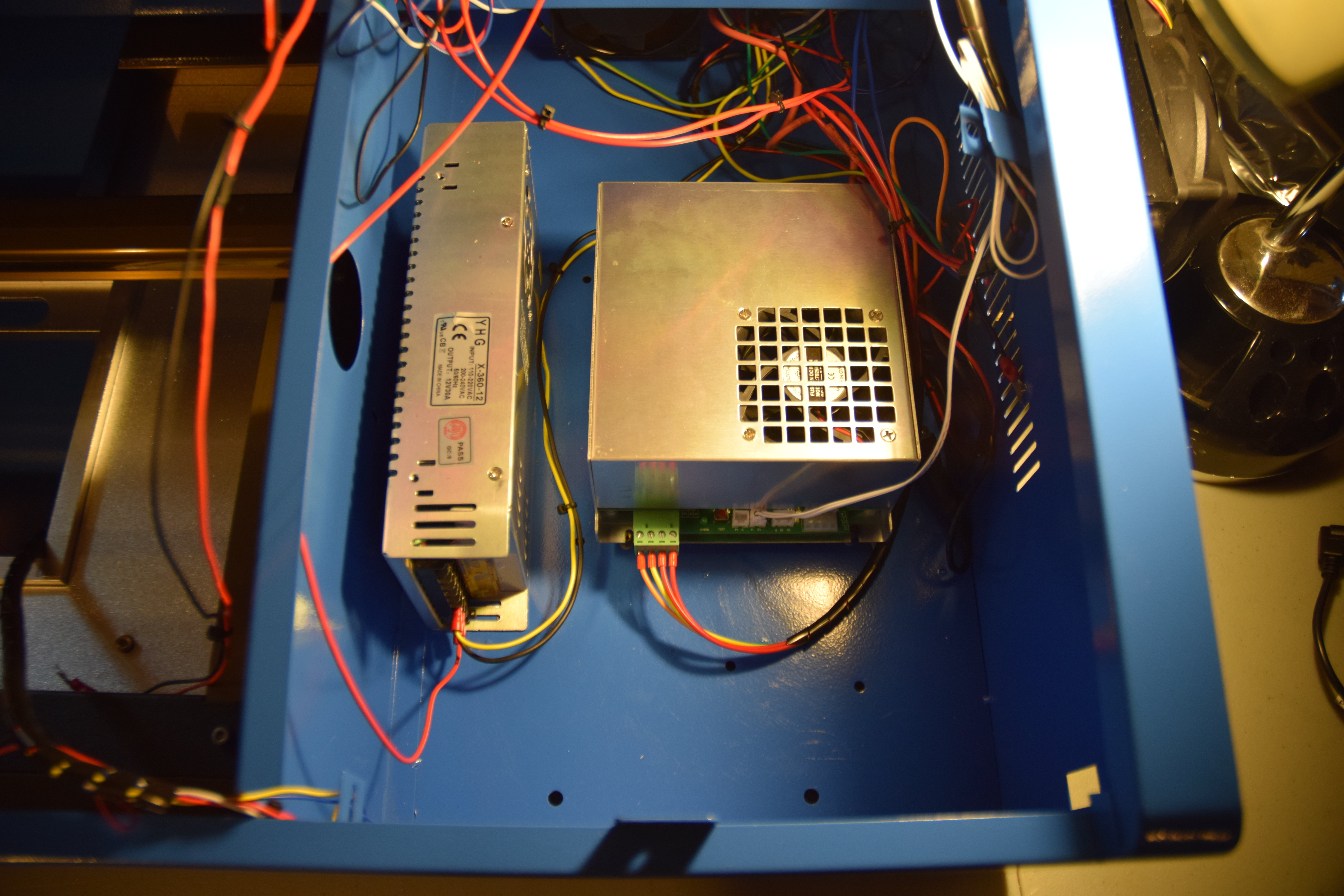
As seen in the wiring diagram, I added a 12VDC 30A power supply for powering all of the additions.
The 12V power supply has 3 sets of power output terminals. The upgrades I have added require 6x connections, so each terminal requires a stack of 2x each, as shown in the wiring diagram. I tried to distribute the current load on each equally.
The current distributions are approximately:
- ACR+Smoothieboard – 4.1A
- Blower – 4A
- LED Strip (27x) – 9x20mA = 180mA = .18A
- Water Pump (4.8W) – .4A
- 120mm Fan – .15A
- Reservoir Thermometer – .018A
- Water chiller (TEC) – 5A
Total current use: ~14A
The power supply was positioned to the left of the laser power supply. The 12V PSU has 4x M4 threaded holes for mount on its side spaced 25mm x 150mm apart. 4x 4mm holes were drilled at that spacing through the bottom of the sheet metal chassis.

Two AC plugs are added for the different components being added. One is for the 12V PSU, one for the air assist pump. Using a dremel, two rectangular holes were cut out of the rear panel above and next to the laser PSU plug.
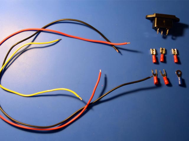
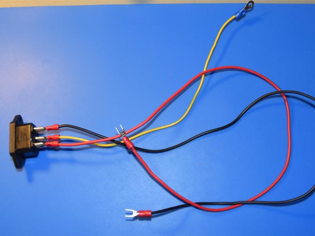
A cable must be made for the ac plug that goes to the 12V PSU. This includes 3 wires: one for positive, one neutral, and one ground. The positive (red) and neutral (black) wires with have spade terminals on both ends, and the ground wire (yellow) has a spade terminal on one side and the other a ring terminal. The ground ring will be attached to the stud on the rear panel of the chassis.
The rest of the electronics changes will be described in their sections below.
Smoothieboard and ACR Setup:
I decided to go with a plug-and-play setup from All-Tek Systems for my new control board. The engineer there, Scott, created a board that makes the transition from the stock motherboard to a Smoothieboard seamless. He sells a kit that includes a smoothieboard, all prewired, and Scott was nice enough to create a custom setup for me that used my 12VDC PSU that I had already installed to my K40 for the other upgrades I made, instead of including a 24VDC PSU (which is typically how the kit comes).

To install, just a couple holes needed to be drilled into the front wall of the electronics box and mount with a couple screws and nuts.
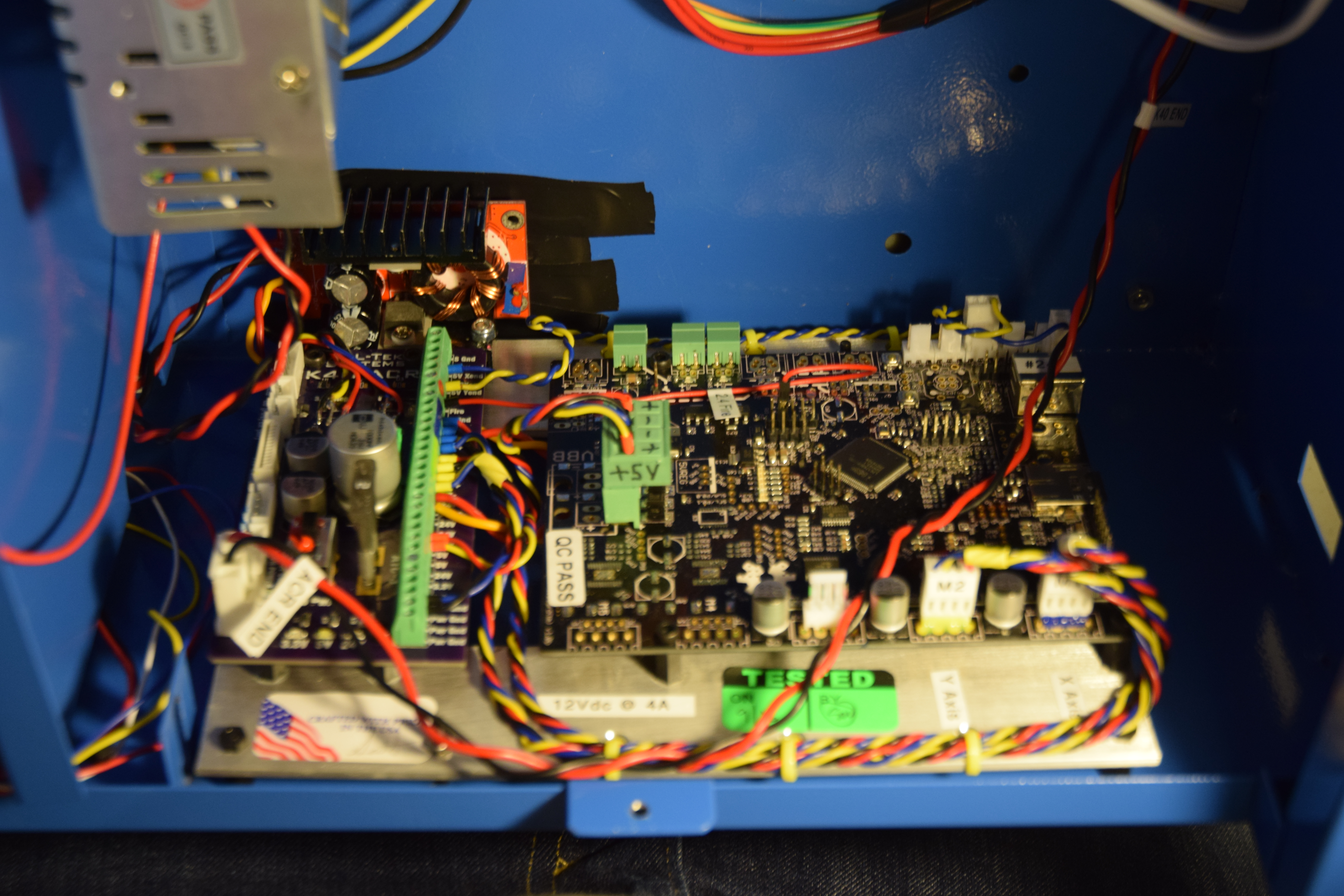
All that needed to be connected were two wires to the 12VDC PSU, the y-axis stepper motor connector, the FFC cable, and a power cable from the ACR to the laser PSU.


And just like that, it is ready to use LaserWeb3!
Along with the ACR+Smoothie Kit from All-Tek, I also got their USB Quick Disconnect. (see webpage for description of item)

This mounts right over the USB cutout on the right side of the K40 chassis using double-sided tape. The USB connector goes to the Smoothieboard and the 2x other wires connect to the ACR board.

Laser-Site Assist:
Adding a laser cross-hair allows you to see the approximate position of the CO2 laser. This will allow you to see where your home position is and see where you are going to be cutting on your material.

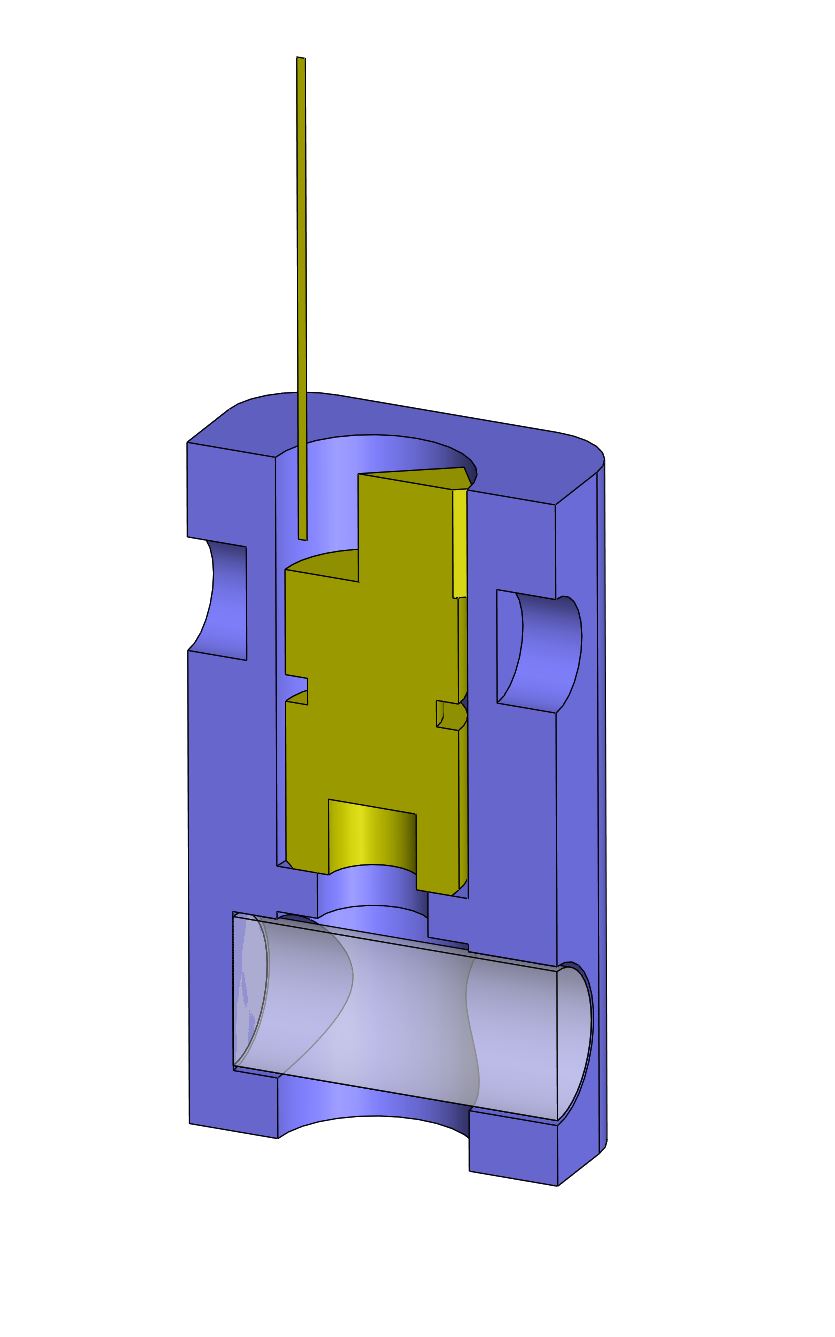
One could purchase a laser that has the cross-hair built in, but I had some lasers that output a point already and decided to make my own. These lasers just give a point, and I needed a line – so I put a glass cylinder immediately in front of the laser to get a line. Two lasers 90 degrees apart from each other, and we have a cross-hair. I designed a mount to be 3D printed to hold the lasers, glass cylinders, and add a nozzle for air assist.
These CAD files for printing can be found on Thingiverse here.

6mm 5V Lasers: Amazon
5mm Glass Cylinders: Amazon
If you follow the wiring diagram you will also need a CR2032 battery, holder, and a switch.

Water Cooling
The pump that comes with the K40 laser is not great. It works, but the one I have has a very “loose” AC cable, so any slight movement of the cable could turn the pump off. That, along with needing a large external bucket for a reservoir made me want to upgrade to a closed-loop watercooling circuit. Using typical watercooling components for PC’s, I did just that.

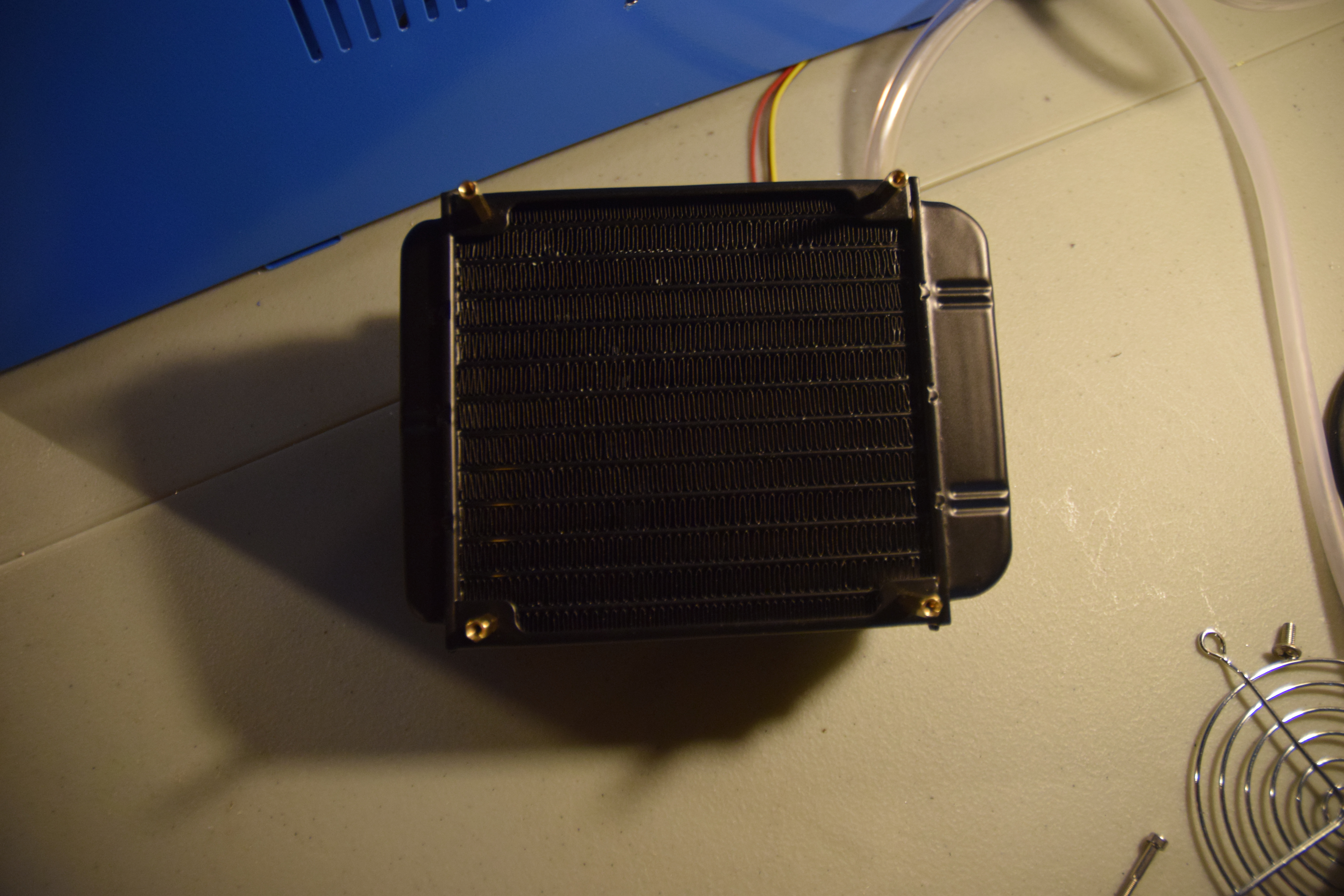
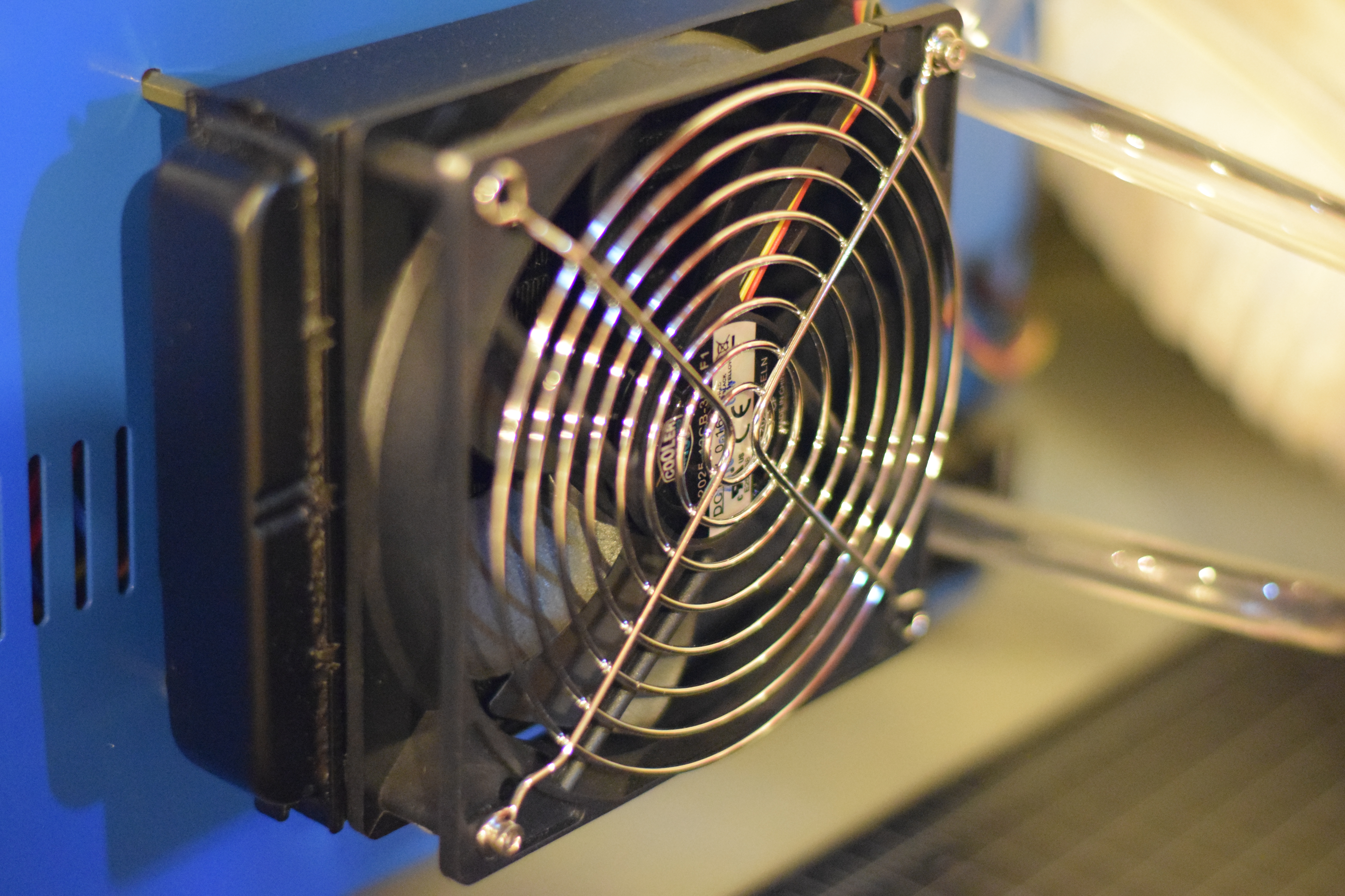
A radiator with a fan mounted to it is used to cool the water as it flows from ther reservoir to the laser tube. This will allow the water to be cooled down to ambient temperature, and no lower. If one wants to drive down the liquid temperature a condenser is needed, or a thermoelectric (peltier) cooler (TEC) (I may replace the radiator with a TEC at a later time). The radiator is mounted roughly centered vertically, 12″ to center from the rear on the right side of the case. It is mounted on 4x M3X18mm male-to-female standoffs. Note: it is important that you have an area all around the radiator that is equal-to or larger-than the area of the radiator/fan so that you are not restricting airflow through the radiator. So, the standoffs should be at least 18mm in length. Simplified calculations:
Fan area = pi*(120mm(diameter)/2)^2 = ~11300mm^2.
Area outside Radiator: 4(# sides)*160mm(length)*18mm(standoffs) = 11520mm^2
The pump is at the lowest point in the circuit to try and facilitate an “always-upward” moving circuit to prevent air bubbles from getting stuck in the tubes. The pump is powered with 12V, so it connects directly to the 12V PSU. The pump comes stock with a 2.1mm x 5.5mm female power adapter, so a cable can be built with a mating connector.

The cable is made of two wires, one positive and one negative. At one end of the cable is the male 2.1mm x 5.5mm power plug and the other are spade terminals that go to the 12V PSU.
For the same reasons, the reservoir is at the highest point of the circuit – so any air in the circuit ends up in the reservoir and stays there. Being a closed-loop system, once you fully “de-air” the circuit the first time you shouldn’t have to worry about air bubbles in the circuit.
The fluid circuit goes:
- pump outlet > radiator inlet
- radiator outlet > laser inlet
- laser outlet > reservoir inlet
- reservoir outlet > pump inlet
The pump came with a mounting clip – so with 2 drilled holes, 2x M3x8mm screws, and 2x nuts the pump can be easily mounted.

The reservoir does not have any good mounting points, so I just used galvanized steel hanger strap to hold it.

To remove the tubes attached to the laser to replace them, I used an Xacto knife and carefully slit the tube down the length that was over the laser barb.

The inlet tube goes through a 12mm hole I drilled on the side of the case. The outlet tube connects to the reservoir barb that also fits through a 12mm hole drilled into the side of the case.
I added silicone RTV sealant to all of the tubing connections to the laser tube as a “backup” in case of a leak. Be sure to give the RTV several hours to cure.

I filled the circuit with distilled water through the plugged port at the top of the reservoir. Using a couple funnels laying around and a piece of tubing I could pour the water in. You will need to have the pump running to get water pushed through as you will likely have a lot of air pockets. I suggest pouring some water in before starting the pump. Fill until most of the air is out of the circuit and such that the reservoir is filled enough that the reservoir inlet (from CO2 laser tube) is completely submerged, but not high enough that water is spilling out of the top port you are filling the circuit with!

You may need to remove the pump from its mounted position to have the outlet sit vertical relative to ground to work properly. Also you may need to lift the whole enclosure in different ways to get all air out of the tubes and especially the CO2 laser tube.
Water Cooling TEC Chiller Assembly
I added a TEC chiller to the watercooling circuit to actively cool the the water. I purchased the watercooling block and TEC chiller from Ebay, which included the heatsink. A switch was added and a DC jack for supplying power. A housing was 3D printed to enclosure the wires and the water block.


Air Assist
I wanted to add a switch to the Air Pump, so I added an AC inlet socket to the rear panel of the enclosure. This required cutting a rectangular hole, with 2x holes on either side, for mounting the AC inlet socket. I used a dremel with a metal cutting wheel to make the rectangular cut, and a drill with a 4mm drill bit for the screw thru-holes.

The first thing I did with the Air Pump was cut the end of the power cable off, stripped about 15 inches of the outer insulation to reveal the 3 wires inside, stripped the tips of each wire and add terminals (3x spades). The Live wire (red) goes to the switch, and the Neutral wire (black) and Ground wire (green) go to the AC inlet socket.

A separate cable is made with 18AWG wire to go from the switch to the Live connection on the AC inlet socket.

After installing the air pump, you can add the tubing. You will need about 3 ft of 1/4″ tubing (actually, you may want something a little larger – I had to heat up the end of the tubing to squeeze it over the pump nozzle).

I routed the tubing through the water outlet hole, which was no longer being used. After replacing the vent, frame, and bed I routed the tube to the laser, where I had a nozzle on the 3D printed assembly for the air. The 3D model can be found on thingiverse, here.

Cover Safety Switch
This is an easy addition and well worth installing. All you need is a mechanical switch, some wire, and some double sided tape.
The mechanical switch goes between the “Test Switch” and the Laser PSU. Adding this additional switch keeps the circuit open when the cover is open so that even if the push button is depressed, the laser is still off.

Because we want the circuit to be open when the cover is open, we want the mechanical switch to be wired to COM and NO (normally open) – not NC (normally closed). About 14 inches of wire to the switch for routing it from the laser PSU to the right sidewall in the cutting bay.

The wires were then spliced with the P+ wire on the test switch cable.

I had laying around a 3D printed part that is not getting used for anything, so I grabbed that to be an extension of the cover so that it could reach the switch. A piece of wood would be fine too.

This piece was glued to the cover with loctite super glue.

A piece of adhesive-backed velcro was used to mount the mechanical switch to the right sidewall inside the cutting bay. Double-sided tape would do just as well (probably better).

Align the switch and cover extension and when the cover is closed the switch will be fully depressed. You now have a much safer laser cutter!
Temperature Sensor Upgrade
Monitoring the temperature of your laser is important because its life will be lowered if ran too hot. A simple addition to the K40 is a temperature sensor with LCD screen.
Amazon: DROK Plug-In Digital Temp Thermometer

By default this one comes with very short lead wires for power and a very short thermocouple.
Splicing in additional wire can extend both of those such that the probe can run out to the watercooling reservoir. Adding wire to the power leads and crimping in spade terminals makes it easy to connect to the 12VDC PSU.

For my setup, I drilled a hole in the back corner of the top of my reservoir for feeding the thermocouple into it. Silicone RTV was then used to seal off the wires in the hole.
A quick test of the LCD and thermocouple:

Internal LED Lighting
Adding internal lights is pretty straight forward with the 12VDC PSU added to the box.

The wires that come stock with the LED strip are a bit short, so additional wire will need to be added to reach the 12V PSU. At the end of the added wire, add a couple spade terminals, and it is ready to mount.

If the lights are added to the bottom edge of the cover, one can fit about 27 LEDs. Additional wire will need to be soldered to the leads coming off the strip for reaching the PSU. I added a rocker switch that is mounted to the control panel for turning on and off. You could also just wire it directly to the PSU so that the lights are always on when the laser cutter is running. The lights have an adhesive on the back, so it can be directly adhered to the cover. That’s it!

Blower Fan Upgrade
The exhaust fan with the laser cutter is less than optimal. A good upgrade is a 3″ 12V Blower fan. This will require an “adapter” of sort for filling the area where the stock exhaust fan sits.

I designed an adapter that could be 3D printed and slide into the tabs where the stock fan sits. The 3D models can be found on thingiverse, here.

Due to the size (9.7″x5″), I sliced the part in half and printed it in two sections. Printing took a total of about 17 hours.

After printing, the two halves were glued together using gorilla glue. (I had a third piece to glue together because of a printer error partially through one of the parts.)

5/16″ Thick x 3/8″ Wide Weather stripping was placed around the perimeter for a better seal on the back face of the chassis. (If you keep the air duct inside the chassis the bottom strip will likely get pulled off by the screw heads that hold the duct.)


Once installed, the blower can be positioned so that it is aligned with the adapter hole and two mounting holes can be drilled.

The blower will need wire added to the two wires that come with it as they’re only a few inches long. Adding ~2′ should do for reaching the 12VDC PSU. Make sure the blower is positioned such that the flow is going outward!
Add a short (~2″) length of tubing between the adapter and the blower inlet and then you can add the rest of the tube to the exit.

Drag Chain
With the air assist and site-assist added, a drag chain is used for cleanliness and to ensure the tubing and wires do not get in places where they should not. This 10x20mm drag chain is a good option (and cheap).

The best(?) position of the cable chain is perpendicular to the laser head for spacial reasons. Drilling two holes on the internal wall separating the cutting area and the electronics area, one end of the drag chain can be attached with a couple screws and nuts.

The other side needs to connect to the laser head gantry, so I designed a mount that could be 3D printed that it could mount to. The 3D model can be found on thingiverse, here.


Route the wires and tubing through the drag chain (prior to mounting either end of the chain for ease) and that’s it!

New Mirrors
One of the stock mirrors got very dirty in my process of aligning the mirrors; so much so that I could not clean it. So, I ordered a set of 3x 20mm OD molybdenum (MO) mirrors to replace all three stock mirrors.

I went with some USA-made mirrors that can be found on ebay for $50 shipped. They seem to be performing well, but they did require some cleaning when they arrived as they were fairly dirty… If I were to order them again, I would probably order from a reputable seller like LightObject, even if they’re a little more expensive.
New Panel
With all of these additions made, the a new control panel needs to be cut out to fit the new switches and the reservoir thermometer LCD screen. I designed a panel in Solidworks (CAD model and two DXF files (one for etching and one for cutting) and used the K40 to etch and cut it out!

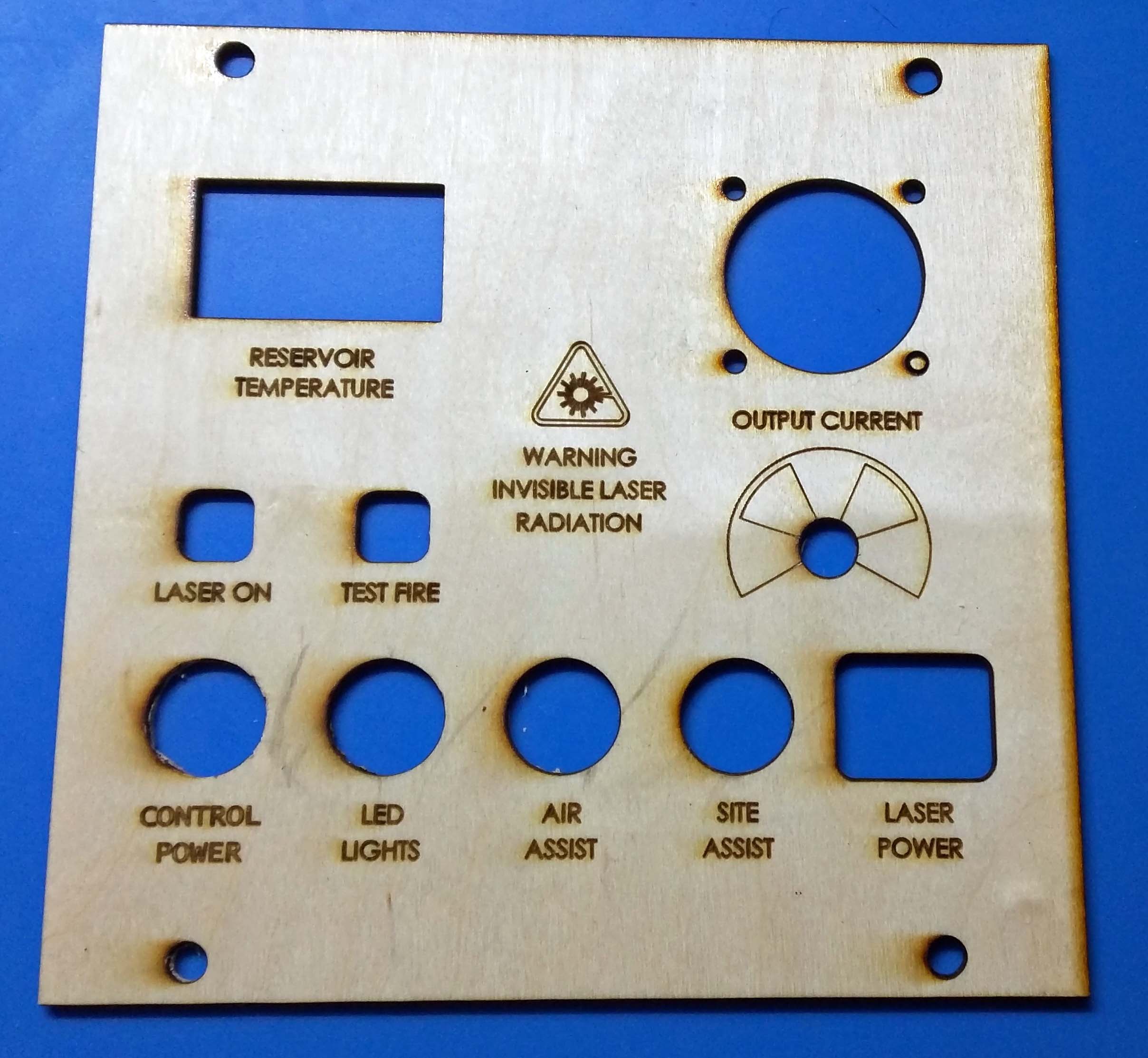
I used 3mm birch plywood, but I may replace it with a colored acrylic. The dxf files can be found on thingiverse, here.

Adjustable Z-Axis Table
I wanted a bed with adjustable height so that I could easily get the material positioned at the focal point of the laser. I saw one manually adjustable bed version on thingiverse (here) and decided to follow a similar design.

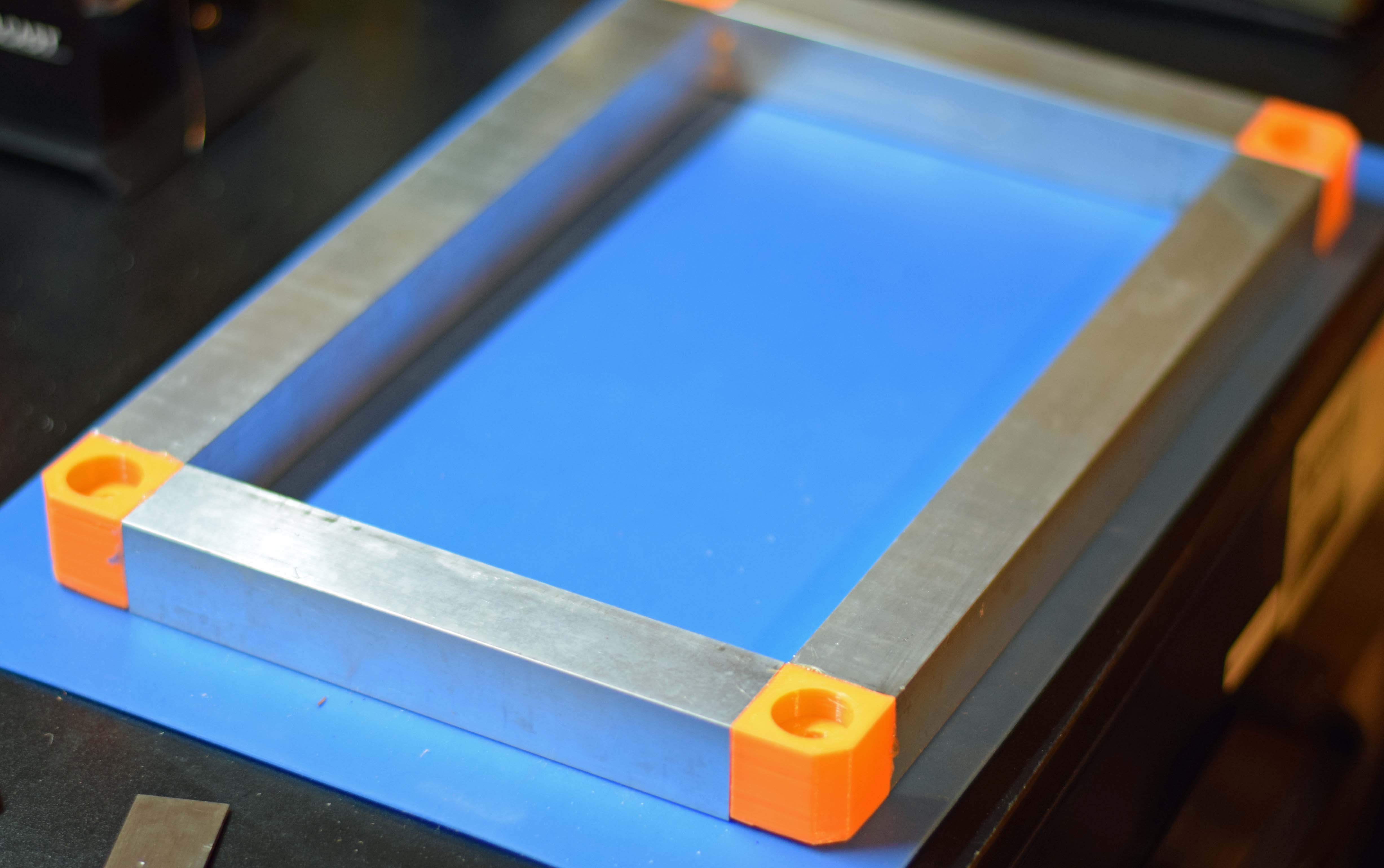
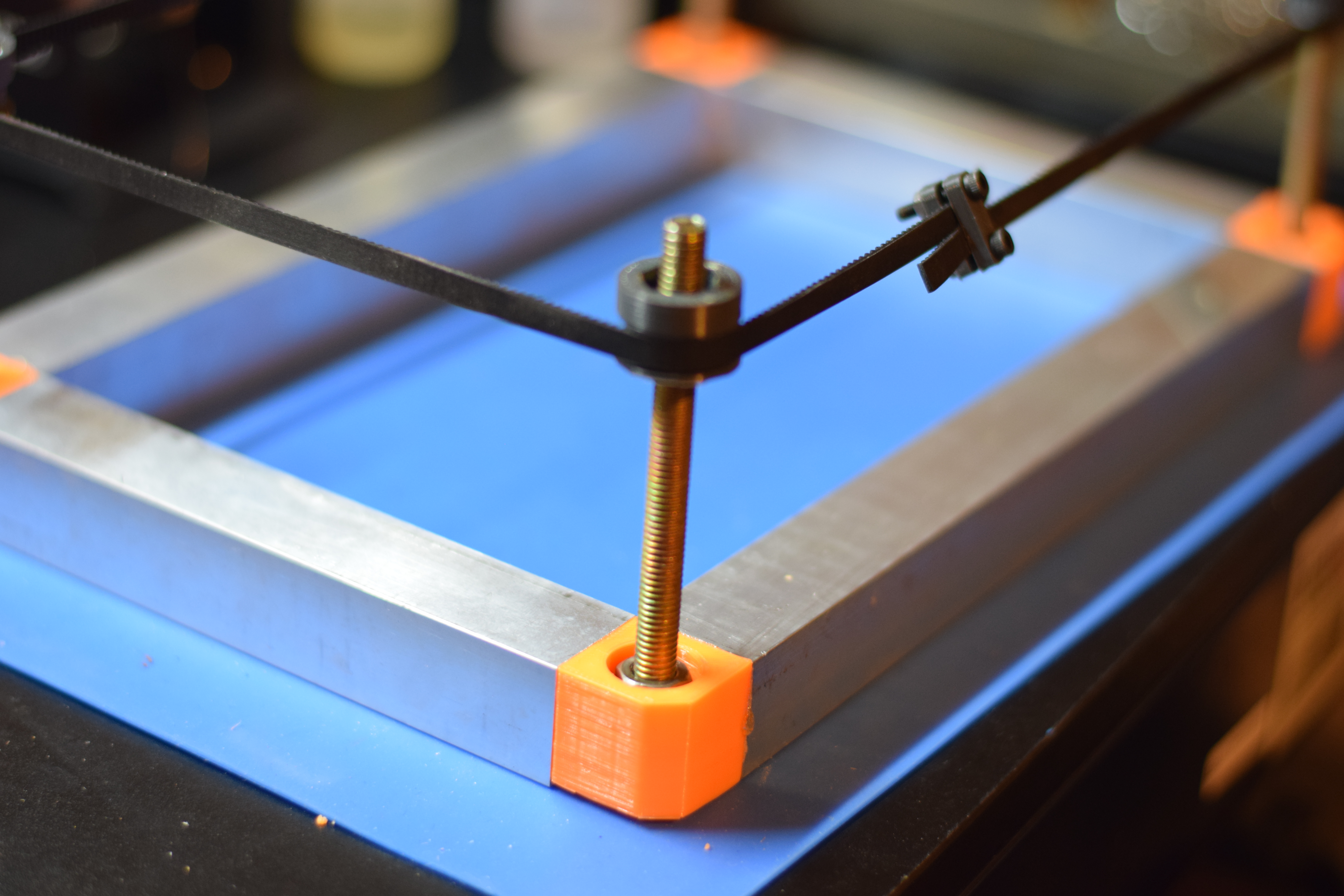
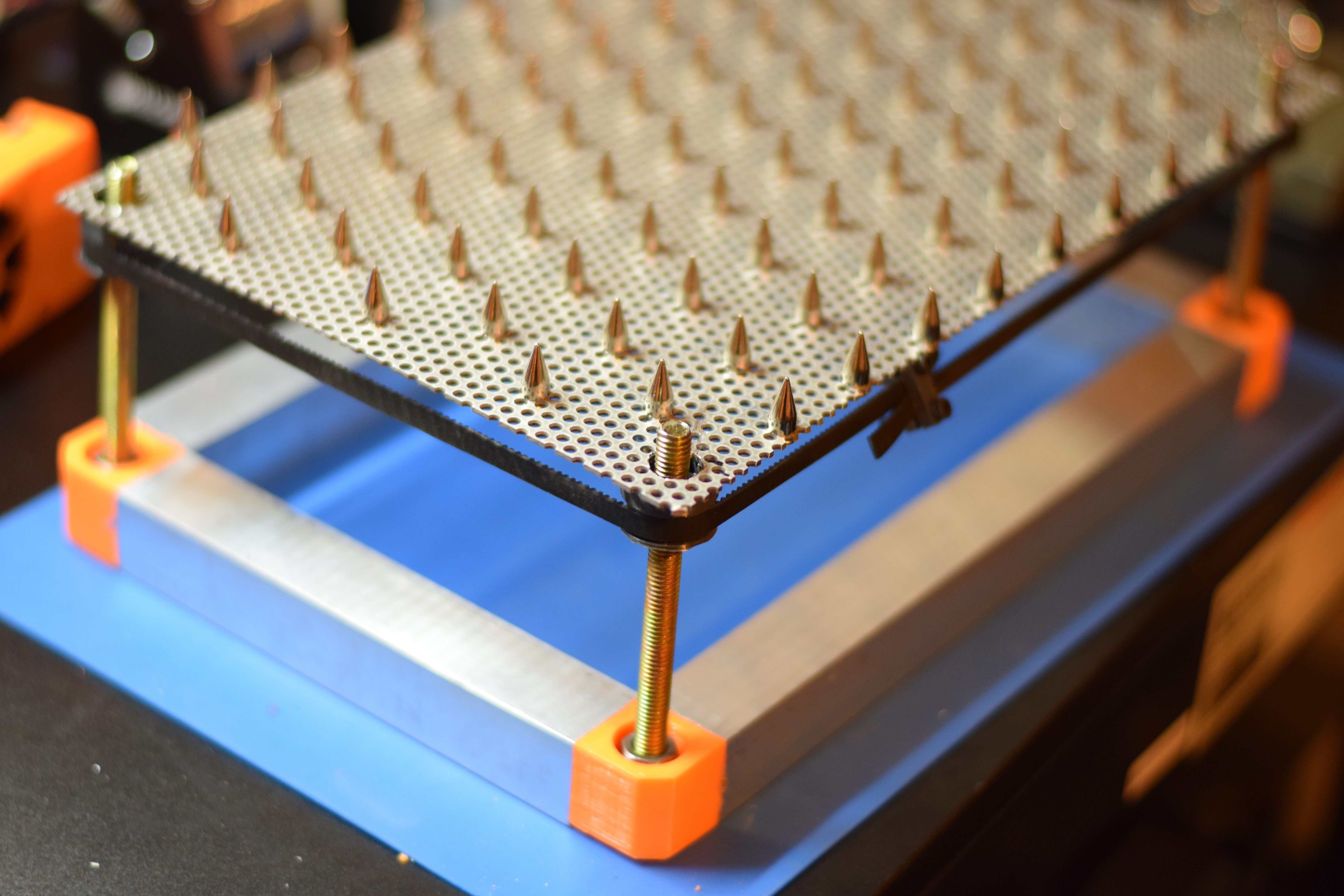
The frame would be 1″ square aluminum tubing with 3D printed corner pieces for joining the tubing as well as for mounting the threaded rods. The bed is a sheet of perforated aluminum and it would sit on 4x 3D printed pulleys (GT2 teeth) that move up and down along the threaded rods in the corners. A belt would be wrapped around the 4x pulleys allowing them to all move in unison. I also added spikes to the bed to minimize the area that the material being cut touches metal. This will prevent burning on the underside of the material due to the laser reflecting off the perforated sheet.
The aluminum tubing was cut to 10″ and 6″ lengths. The perforated sheet was cut to 12″x8″ (same size as the outside dimensions of the aluminum tubing when assembled). The corner pieces were glued in place with gorilla glue (only thick glue I had on hand). The corner pieces have a hole for the 8mm threaded rods to sit and the rod is held in place with an M8 nut on either side of the corner piece.


M8 nuts are glued in place to the pulleys.

With the threaded rods in place and the pulleys threaded on, the belt is wrapped around the 4 pulleys and cut such that there is an inch or so of overlap.
The spikes were screwed onto the perforated sheet in a staggered pattern and it just sits on top of the pulleys.

I then drilled out 4x holes (centered on the 4x aluminum tubes) and 4x holes in the chassis of the laser cutter. With some M3 screws I secured it in place, and it was done!

After getting the bed installed I decided I should have made it a little wider so that I could fit 12″ wide material (the threaded rods prevent that). Maybe I will order some more material and rebuild it a little wider…
That’s it for the upgrades I am planning for the laser cutter. Hopefully you have found it helpful with your own upgrades. If you have any questions, give me a shout. Cheers
